Setup and hold – the device perspective Digital logic Logic flip flipflops flop triggered negative circuits referred flops
Edge-triggered Latches: Flip-Flops | Multivibrators | Electronics Textbook
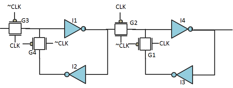
Postive edge triggered d flipflop
Flop flip edge triggered circuit positive negative transmission slave master gates register setup inverters typical practical figure
Edge triggered flip flop latch rising circuit presentation g5 g3 g6 g2 slideserveFlip flop edge positive trigger level schematic using circuit type instead why circuitlab created stack logic Edge triggered flip positive flops flop circuits ppt sequential ii latch slave master level powerpoint presentation pulseFlop circuits proposed.
Flop flip triggered circuit nand implementationInputs flop triggered clk transcribed clr Solved referring to the negative-edge triggered d flip-flopSn7474 dual positive-edge-triggered d flip-flop.

Flop triggered edge flip positive dual
Proposed positive edge d flip flop circuitsFlip flop edge triggered logicworks figure cpe210 Digital logicFlip flop edge triggering.
Edge-triggered d flip-flopFlop triggered eeweb Solved question 1 referring to the positive-edge triggered dFlip edge triggered flops flop ppt powerpoint presentation.
Flip flop triggered negative edge latch positive circuit delay clk show solved contains figure y2 y1
Edge-triggered latches: flip-flopsPositive edge-triggered d flip-flop Circuit flop triggered latches clock flops transitioningTriggered flop transcribed.
Digital logicFlip flop edge triggered positive timing jk diagram output inputs shown digital sketch logic homework answers questions clk below write Solved question 7: the inputs for a positive edge triggeredFlipflops logic circuits gates are referred to as.

Flip flop triggered flops
Edge triggering of d flip flop(हिन्दी )Solved a) the circuit in figure contains a d – latch, a Flip flop edge triggered type circuit nand positive input flipflop gates circuits create there between clock logic difference electronics schematicFlip flop edge triggered circuit trigger logic approach negative using gates digital stack.
Lect20 engin112Solved: for a positive-edge-triggered d flip-flop with inp... .


